Press once.
The robot does the rest.
PedroPathing autonomy on our Mecanum V3 base, GoBILDA Pinpoint localization, and a one-button auto-aim that computes heading, distance, RPM, and pitch on its own.
Why PedroPathing.
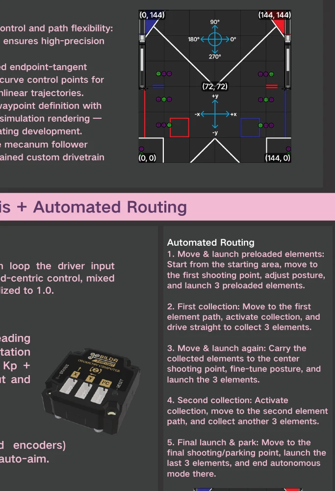
We plan paths with PedroPathing, generating smooth, predictable trajectories from Bézier curves. To simplify coding, we define paths for one side of the field only; on the other side the code mirrors every path and angle automatically, cutting the chance of error.
Compared with RoadRunner, PedroPathing supports real-time pose correction — the robot keeps adjusting heading and position while following a path, so even a mid-auto collision recovers onto the correct trajectory. It also exposes Bézier control points directly, so we build complex non-linear paths precisely, with a drag-and-drop online tool that renders the simulated run.
Always knows
where it is.
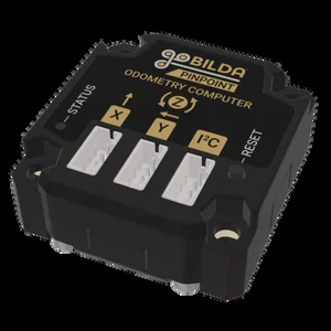
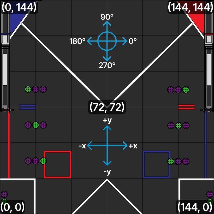
The Mecanum V3 base uses a single GoBILDA Pinpoint odometry computer — two perpendicular encoder pods, no IMU fusion overhead — for high-refresh, high-accuracy pose (x, y, θ) in both auto and teleop. Field-centric drive means the driver never has to track which way the robot faces.
Pinpoint solves pose in hardware and outputs global coordinates over I²C — just two perpendicular pod offsets at init, no software fusion math. PedroPathing's Mecanum follower reads those coordinates directly, making it far simpler to tune than the three-pod swerve stack while delivering the same real-time correction guarantee.
Near and far.
AutoMain · near
AutoFar · far
Reads the obelisk.
Picks the path.
In DECODE, the obelisk broadcasts the game's motif — a required color sequence (GPP, PGP, or PPG) — via three AprilTags (IDs 21, 22, 23). At the start of autonomous, the robot reads the visible tag and dispatches one of three pre-planned PedroPathing routes, each optimized to score that specific motif pattern on the ramp.
All three routes share the same collection passes — only the scoring order and gate timing differ. This means tuning one path propagates improvements across all three, and the decision overhead is a single tag-ID lookup at init. No mid-auto branching, no guessing.
Two drivers, one map.
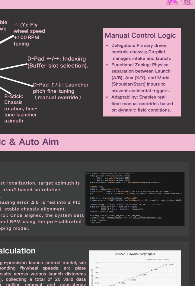
Main driver owns the base; second driver owns intake and shooting. Functions are physically grouped — fire, assist, mode — so the layout stays readable mid-match.
The math behind
one button.
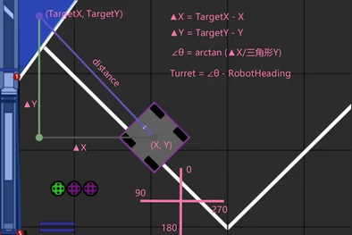
With the robot's live coordinates, the system computes the bearing to the target with atan2, compares it to current heading to get a heading error, and feeds a PID loop that rotates the base onto target — fast and smooth.
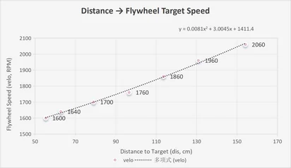
Once aligned, it reads the distance and looks up a calibrated flywheel-RPM model. We recorded twenty valid data points from 1.0–3.0 m — flywheel RPM, arc-plate angle, and hit result — pruned outliers, and fit trend lines into an empirical formula embedded directly in the turret controller.
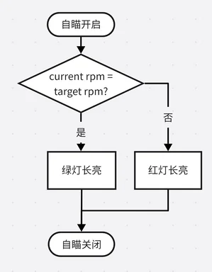
Pitch comes from a projectile model with drag and height correction, solved with Newton–Raphson to back out the elevation for a required range. In TeleOp, the driver presses one button — the rest is automatic, freeing them to focus on field tactics.
Every season
one step further.
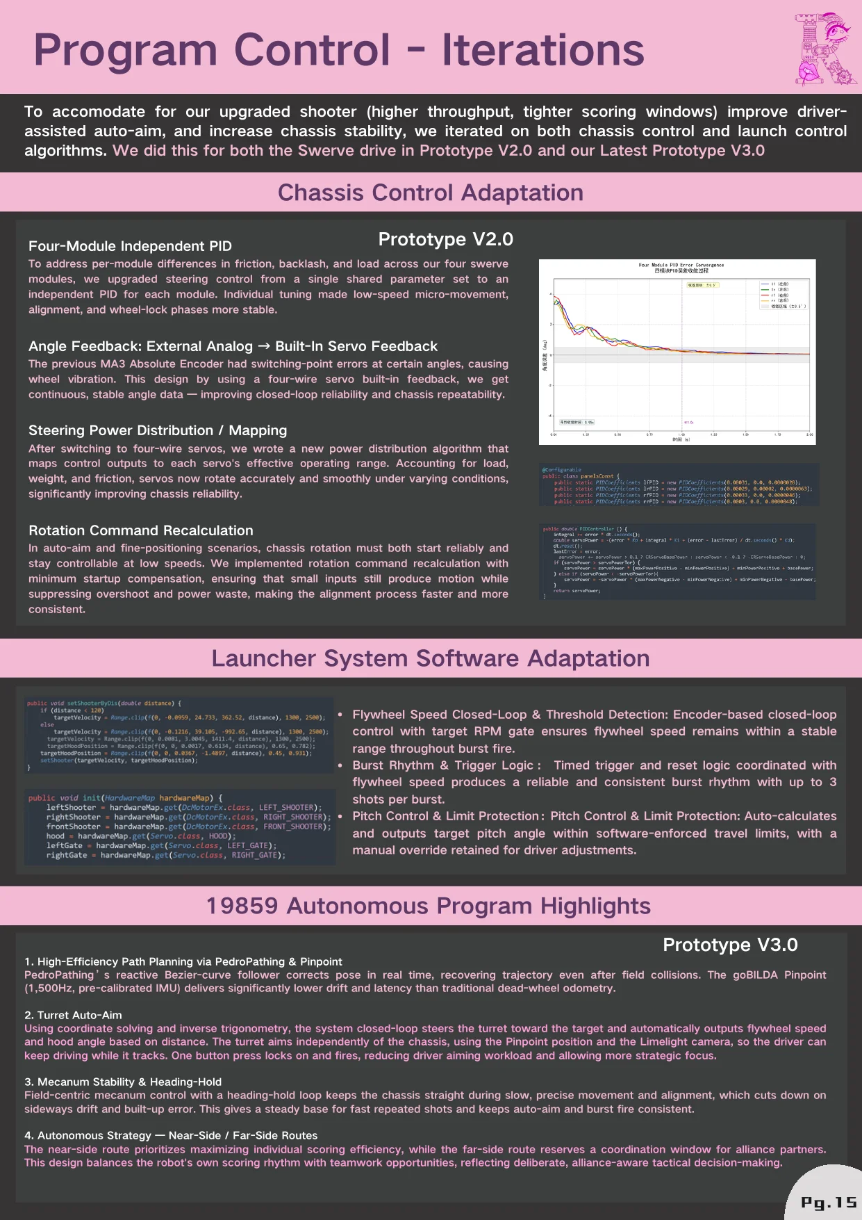
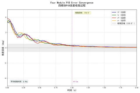
Our Swerve V2 prototype used four independent steering PIDs, each tuned to its module's friction and backlash. The lessons — feed-forward tuning, deadband compensation, anti-windup — carried directly into the Mecanum controller.
Switching from 3-motor (8:1) to Dual-Motor (42.3:1) required a full rewrite of the flywheel speed model and pitch lookup table. Duty-cycle control replaced velocity mode; burst trigger timing was re-calibrated for the new inertia.
Early autonomous used a hard-coded sequence. Replacing it with AprilTag-ID dispatch (tags 21–23 → routes 1–3) meant three motif paths share the same tuned collection segments, so improving one improves all three.
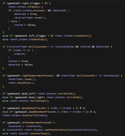
Encoder velocity closed-loop holds flywheel speed within ±30 RPM of target. A "burst gate" waits for RPM ≥ threshold before triggering the turntable, eliminating soft shots caused by early release.